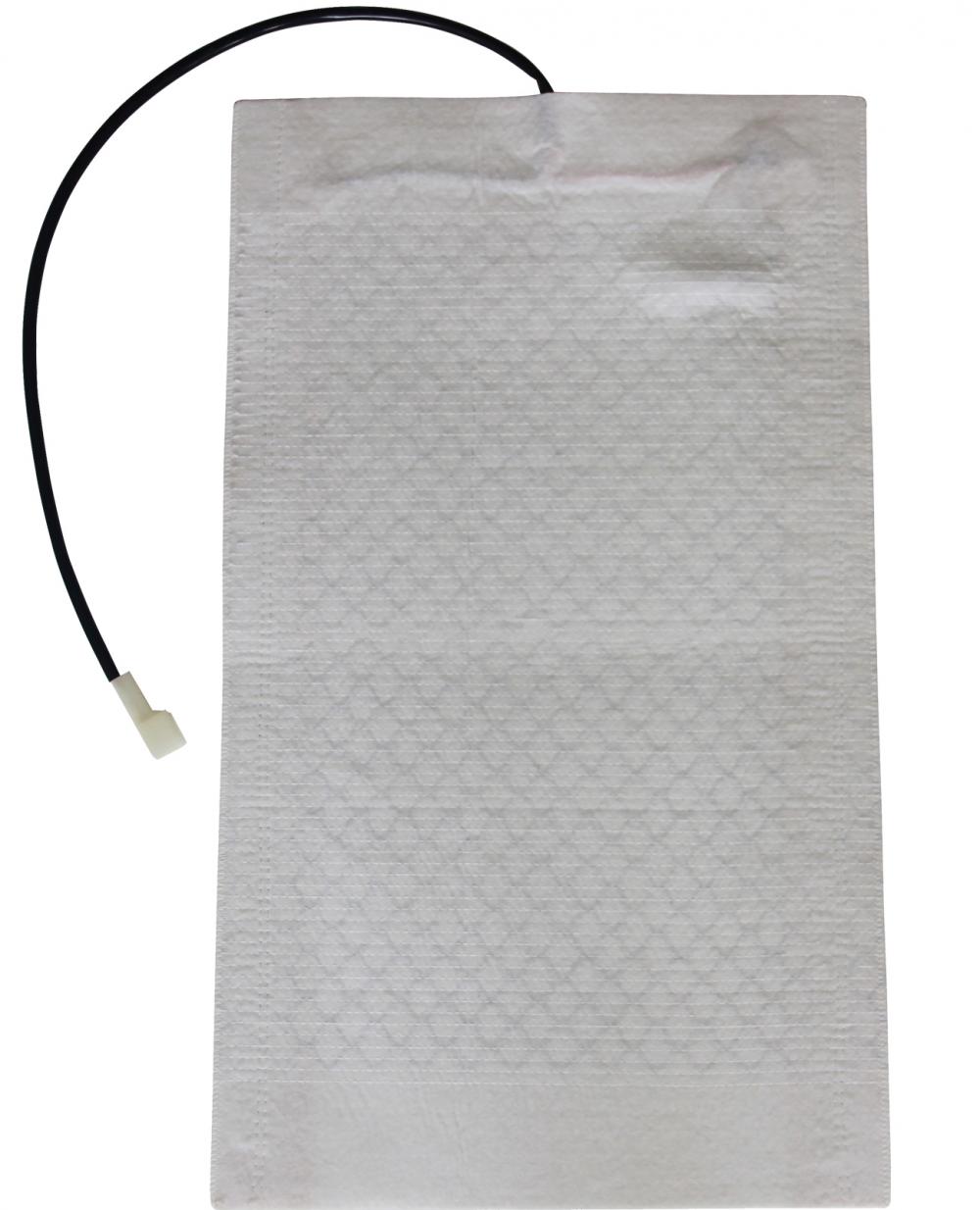
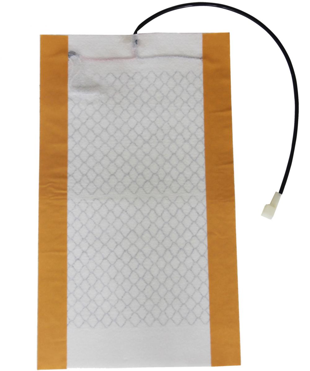
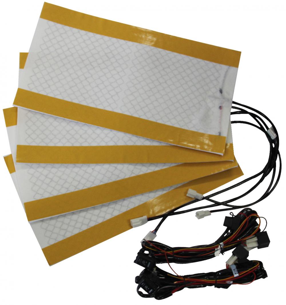
With a pack of two seats, it provides you with what you need for the car when traveling. The two seats have been designed to provide efficient heating as you get to adjust the temperature from 30 minutes to 60 minutes. Furthermore, the seats are very comfy thanks to the quality cushions and large sizes. Heated Cover,Heated Seat Carbon,Metal Stainless Heated Pads,Car Heating Carbon Fiber Pad JiLin Province Debang Auto Electric Co.,Ltd. , https://www.dbheatedpads.com


YA type circular vibrating screen use instructions (2)
1 , repair and maintenance
(1) When the screen is shipped from the factory, the vibrator is filled with lubricating oil and has anti-corrosion performance, which is valid for three months. The storage period is more than three months. For each re-run for 20 minutes, the anti-corrosion can be continued for three months. When working, replace it with clean lubricating oil.
(2) Always keep the vibrator vent hole unobstructed, and if it is blocked, it may cause oil leakage. If there is still oil leakage after unblocking, the oil seal should be replaced.
(3) The normal operation of the bearing should not exceed 75 °C. The new vibrator may have a slightly higher temperature because of a running-in process, but after 8 hours of operation, the temperature should be stabilized. If the temperature continues to be too high, the oil should be checked. The level, oil level and cleanliness of the oil.
(4) Ensure that the labyrinth tank is filled with grease, and if it is working under a large amount of dust, it should be filled with grease more frequently.
(5) When replacing the triangular tape, the motor foot should be completely loosened, and it should be conveniently placed in the tape wheel slot. Do not use the stick or other objects to clamp the triangle tape. The tension of the triangle tape must be suitable. The tape wheel must be aligned. After adjusting the tension for the first time and performing 48 hours of work, re-adjust it once.
(6) The bolts connected to the vibrator and the screen box are high-strength bolts. It is not allowed to replace them with ordinary bolts. The tightness must be checked regularly, at least once a month. If any one of the bolts is loose, it will cause other bolts to be cut and cause damage to the screen.
(7) where the use of rivets coupling the ring groove, allows high strength bolts in place, all the contact surfaces or holes, should look no ash, oil, rust, iron shavings and burrs.
(8) The high-strength bolts, nuts and washers used must meet the requirements of GB1231—76 “Technical conditions for high-strength large hexagon bolts, large hex nuts and washers for steel structuresâ€. The torque applied continuously was in accordance with Table 1 below.
Table 1
Bolt diameter (mm)
16
20
twenty two
twenty four
Torque (N·m)
237
420
678
1007
[next]
(9) In order to prevent internal stress caused by welding, it is generally not allowed to weld the screen box and any auxiliary parts on site. When welding, it should be carried out by skilled operators. The following steps are recommended.
a To prevent crack propagation, drill a 6 mm diameter hole at each end of the crack.
b Use a round shovel to shovel the crack along both sides of the crack.
c preheating around 60 °C, using a 3mm diameter 506 welding rod, and to prevent any slag and bite.
d Smooth the solder on both sides and weld the reinforcing plate.
e If it is necessary to weld on the screen bracket beam, all welds shall be parallel to the beam and shall not be welded laterally.
f When using AC welding, the screen slip should be grounded to prevent current from passing through the bearing, otherwise it will easily cause damage to the bearing.
(10) When the flame is cut, stress is also generated around the cut surface. Therefore, it is recommended that any additional holes on the screen box should be drilled.
(11) Between the woven screen and the screen bracket, a special damping rubber strip is provided, as shown in Fig. 1. In order to achieve the longest service life of the screen, the rubber strip should be properly placed between the two, and the damaged vibration-damping rubber strip should be replaced in time.
Figure 1 Screen tensioner
201-damping rubber strip; 202-screen bracket; 203-screen box side panel;
204-tension bolt; 205-guide angle steel bolt; 206-double hole pad;
207-guide angle steel; 208-tensioning plate; 209-screen; 210-intermediate compression fan steel
[next]
(12) When replacing the woven screen, ensure that there is an equal gap between the two sides of the screen box and the screen hooks. After tightening the intermediate flat steel, tighten the tension plates on both sides to maintain the surface tension of the screen. Evenly, and gently tap the whole length with a hammer to check the tension. If the contact is not good, the tension is not enough or uneven, which is one of the important reasons for the premature damage of the screen.
(13) The tensioning plate guiding angle steel is adjustable. When installing the screen, the guiding angle steel bolt should be loosened so that the upper and lower parts can be moved. After the screen is placed, the tensioning plate is first tightened to give a tensioning plate. After a slight pressure, the guide angle is driven until the screen abuts against the screen bracket and the angle bolts are tightened securely.
(14) In order to properly tension the screen, the length of the screen hook must be the same as the length of the tensioning plate.
(15) When the screen aperture is less than 16 mm, the screen needs to have a 20 mm extension for lap joint at one end, as shown in Figure 2. (There is a screen on each screen surface that does not leave this extension, located at the discharge end).
Figure 2 Screen lap joint
(16) When disassembling the vibrator, refer to Figure 4 and carefully remove the parts from the outside to the inside to avoid damage to the parts. In particular, when removing the balance wheel, be sure to use the detacher, as shown in Figure 3.
Figure 3 balance wheel disassembly
1, flat steel; 2, remove the core rod; 3, remove the bolt
[next]
Figure 4 vibrator
101-eccentric shaft; 102-shaft cover; 103-bearing; 104-tape wheel; 105-shaft end gland;
106-bolt; 107-washer; 108-bolt; 109-washer; 110-isolation ring; 111-seal plate;
112-bolt; 113-washer; 114-bearing; 115-high-strength bolt; 116-high-strength nut;
117-high strength washer; 118-O type seal ring; 119-O type seal ring; 120-vent plug;
121-venting cap; 122-oil cup; 123-seal; 124-oil seal; 125-balance wheel;
126-key; 127-eccentric block; 128-screw; 129-washer; 130-oil level check rod; 131-drain plug
(17) The removed parts should be cleaned and carefully inspected. If damage is found, it should be repaired or replaced in time.
(18) A vibrator is assembled with reference to FIG.
[next]
a Must be carried out in a clean operating environment, and each part to be installed must be clean, free of burrs, and does not affect the performance of the whole machine.
b Do not use a sledgehammer to directly hit a part or force a part to assemble.
c All bolt holes can be fastened one behind the other.
d If one bearing is damaged, usually another bearing is affected and damaged, and replaced at the same time.
e When mounting the bearing, for the YA140 and YA170 type housings, there is a projection on the inner surface of the housing hole. The bearing should be placed close to the side of the high platform. For the YA110 type bearing housing, it should be a through hole, and the bearing should be 6mm away from the outer surface.
f The correct way to install an “O†seal is to roll into the groove.
g When installing the bearing housing, make sure that the oil drain plug is at the bottom of the bearing. For easy installation, use two long bolts to the bearing housing in the shaft housing.
h Install a gasket on the sealing plate to ensure that the gasket does not cover the check oil return tank.
i Grease as much as possible in the labyrinth between the seal plate and the spacer ring.
j When installing the sealing plate on the housing, make sure the oil level check hole is below.
After the k-axis is fixed in the vibrator, check the axial yaw amount, which should be between 2 and 4 mm.
l Ensure the correct amount of oil and the degree of bolt tightening.
2 , spare parts and wearing parts
For the 1-2 sieves, the recommended number is shown in Table 2. If 3-6 sieves, it should be twice the number shown. If 7-12 sieves, it should be three times the number shown.
Table 2
Serial number
Part Number
name
Quantity
Serial number
Part Number
name
Quantity
1
103
Bearing
2
9
Triangle tape
1 set
2
114
Bearing housing
2
10
201
Vibration damping rubber strip
1 set
3
115
High strength bolt
1 set
11
204
Tension bolt
1 set
4
118
O-ring
2
12
208
Tensioning plate
1 set
5
119
O-ring
2
13
209
Screen
6
120
Vent plug
2
14
301
Damping spring
1 set
7
121
Vent cap
2
15
305
Damping block
4
8
124
Oil seal
2
16
306
Damping spring
4
3 , parts ordering
When ordering parts, please provide the following information.
(1) The name of the vibrating screen, the factory number.
(2) The name and part number of the component.
(3) The quantity required.
(4) Determine the mode of transportation.