(1) Principles for the arrangement of construction equipment in the well The main construction equipment in the well during the construction of the shaft includes: buckets, rock grabs, drill stands, safety ladders, pumps, etc. 1. Arrangement of the bucket The bucket should be placed away from the centerline of the wellbore and placed close to the side of the hoist. Multiple sets of lifting arrangements should make the derrick evenly stressed. When lifting with double hooks, the safety gap between the two protrusions between adjacent lifting containers should be maintained. When arranging the bucket in the wellbore that needs temporary re-twisting, the orientation requirements of the temporary cage lifting during the construction of the yard should be considered. When the bucket passes through the bell mouth, the safety clearance between the most protruding portion and the orifice meets the requirements. 2. Arrangement of rock grab machine The central slewing rock grab should be offset from the center of the wellbore. The center slewing rock grab must be separately provided with a protective rope. When the rock grab is deactivated, the distance between the most prominent size of the grab and the bucket should not be less than 500mm safety clearance. 3, the arrangement of the umbrella drill When the umbrella drill stand is not working, it is generally parked at the wellhead. In order to ensure the convenience of drilling the well every time, the lower part of the wellhead should have enough lifting space. When working underground, it must ensure that its support is reliable. Generally, the central slewing rock grab is used to protect the hook head from hanging downhole. 4, the arrangement of the pump Generally close to the well, the safety distance between the well and the well wall should be guaranteed to be 300mm. 5, the layout of the pipeline The safety ladder should be suspended near the well wall and the maximum distance from the well wall should not exceed 500 mm. At the same time, it is necessary to avoid the hoisting ring beam and the rock grab track, and the safety ladder should be able to descend to the working surface. (2) Principles of layout of the Tianlun platform The center beam axis of the sky wheel platform must be perpendicular to the shaft center of the sinking well, so that the maximum lifting dynamic load during the drilling is consistent with the direction of the maximum bearing capacity of the derrick. The axis of the beam in the skywheel platform should be away from the centerline of the wellbore parallel to it and shifted to the opposite side of the lifting bucket to facilitate the lifting of the bucket to the cage. When the sinking equipment needs to suspend the same equipment with two sinking winches, the two balance wheels should be arranged on the same side so that the direction of the ropes is the same. The double-rope suspended pipeline should be suspended by a double-slotted sky wheel. Lifting the skywheel should be arranged at the same level as possible, and generally do not make a high-low one. The stable rope wheel should be arranged on both sides of the lifting wheel, and the direction of the rope is the same as that of the lifting wire rope. Set as few guide wheels as possible, and if necessary, pull out the rope under the side beam of the skywheel platform. The clearance between the suspended wire rope and the sky wheel platform member shall be not less than 50 mm; the space between the sky wheel and the sky wheel platform shall be not less than 60 mm. (3) Arrangement of construction discs in the well The arrangement of the discs in the well includes the arrangement of the beam and the orifice of the disc and the arrangement of the construction facilities on the panel. When making arrangements, please refer to the following requirements: The hanging ring beam is generally a closed circular beam. The main beam of the hanging plate must be a complete steel beam, generally parallel to the lifting center line, and the two beams are arranged symmetrically as much as possible. The suspension points of the hanging plate are generally arranged symmetrically, so as to avoid the position of the tank path and the tank beam in the well, so as to avoid re-modifying the hanging plate when the wellbore is installed. It is necessary to stagger a certain distance between each suspension beam of the hanging plate and the fixed plate and the sealing plate. It is strictly forbidden to pass through the beam of each wire of the wire rope. The measuring hole of the wellbore center must be set on the hanging plate. The specification is 200mm×200mm. When the hanging plate is suspended by a single rope, the hanging wire rope should be 250-400mm away from the core of the wellbore. When using the umbrella drill to make the eye, in order to fix the umbrella drill in the center of the wellbore, the displacement hole of the 100mm wide parachute wire rope should be left on the hanging plate. The base of the slewing mechanism of the central slewing rock grabber shall be installed on the two steel beams of the hoisting disc. The inner margin of the two steel beams shall meet the installation requirements. A safety clearance of 100-200 mm should be left between the outer edge of the bottom bell of the lower part of the hanging plate and the arm of the central rotary rock grab to avoid collision or affect the rock grabbing range of the rock grabber. Sealing discs, hanging discs, and movable door panels should have reliable sealing measures when not in use to avoid falling objects. ①Hardness:
Due to the scientific synthesis of high-molecular polyurethane elastomer materials using iron rubber, the higher the hardness, the higher the modulus, the smaller the elongation, and the better the wear resistance and heat resistance. Well, in the range of minus 35 degrees Celsius to 100 degrees Celsius, and at a pressure of 60 to 70 MPa, the maximum sealing performance can be guaranteed.
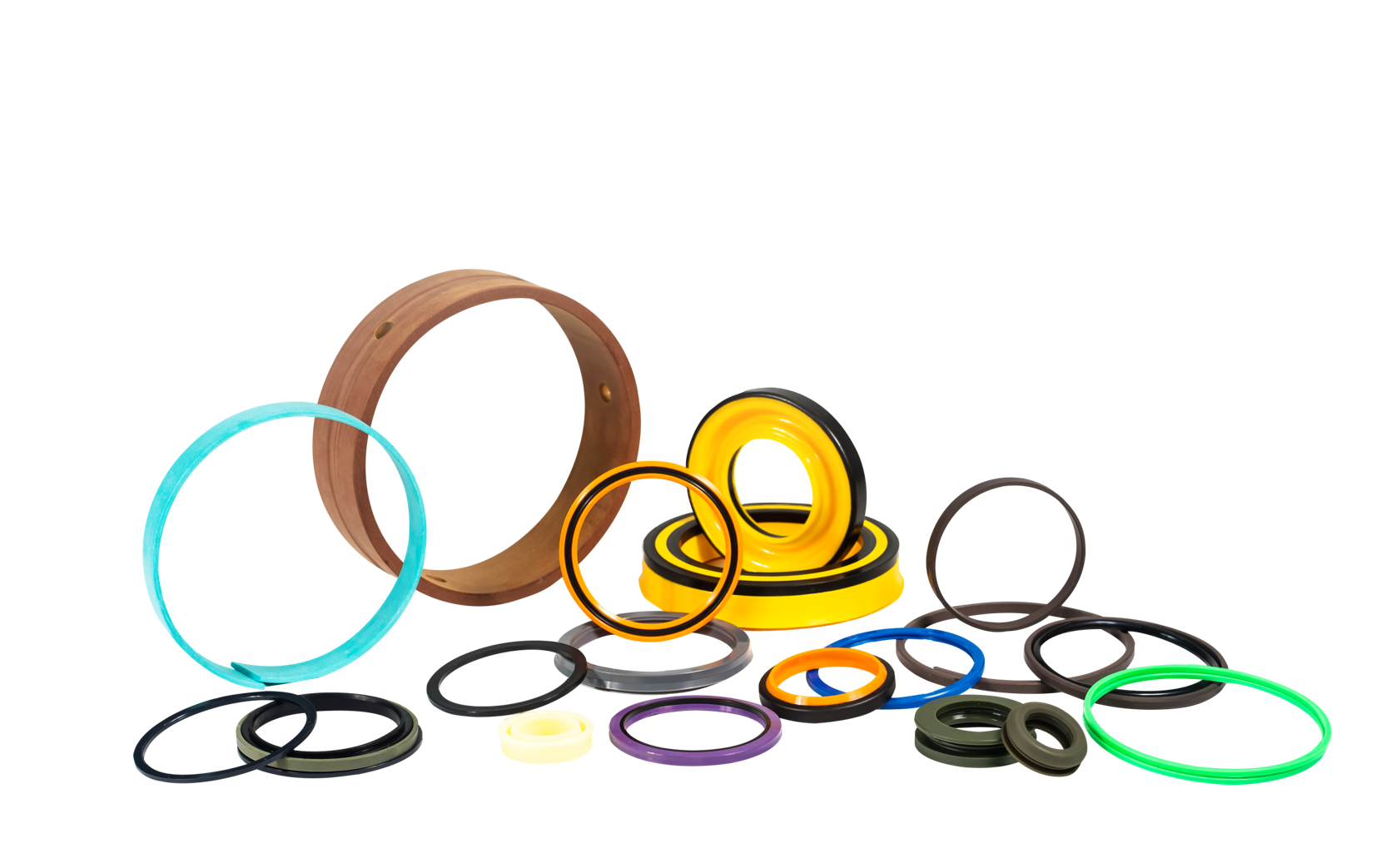
The use of viscoelastic seals made of nitrile rubber is the most complete protection against damage caused by back pressure. In the range of minus 55 degrees Celsius to 100 degrees Celsius, and under a pressure of 21MPa, due to the rubber The seal is often in a compressed state, so the compression performance of the rubber seal must be considered. It not only achieves enhanced anti-climbing performance and low friction resistance, but also has good performance in dealing with special low-temperature oil, and can also be used in combination with Anti-wear Ring double-purpose retaining ring BRL type.
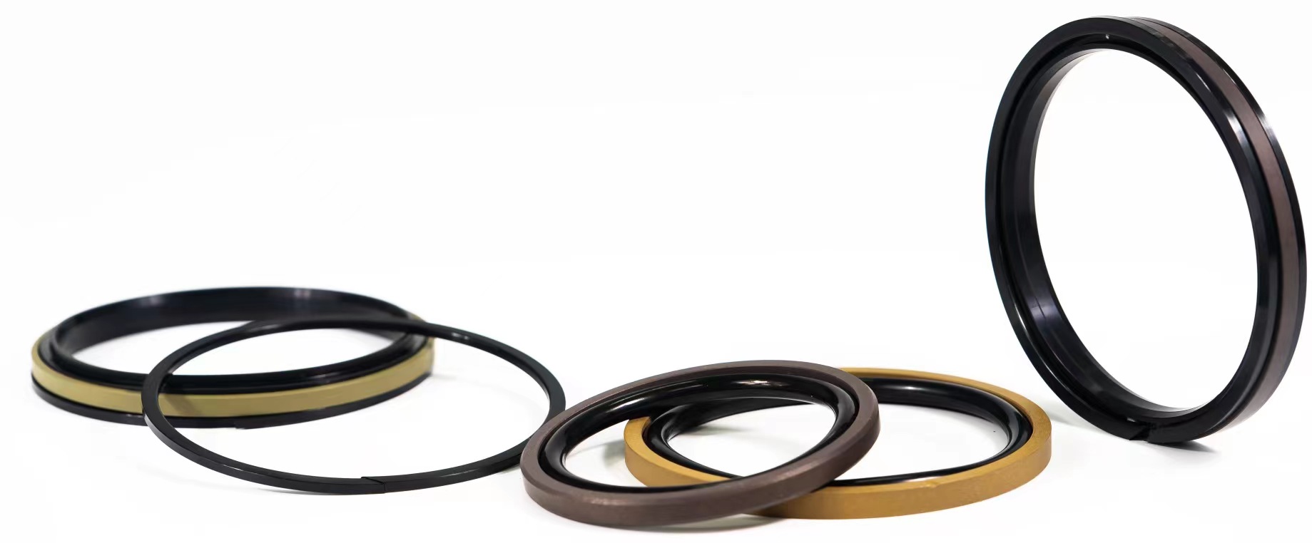
Sealing products made of polytetrafluoroethylene and nitrile rubber/PTFErubber; or seals made of nylon resin and nitrile rubber, which can be used in a wide range of applications with large pressure changes and fast sliding speeds According to the working condition, the input hydraulic pressure cutout is designed on the end face of the polytetrafluoroethylene ring to prevent penetration leakage. The maximum working temperature environment is minus 40 degrees Celsius to 160 degrees Celsius; the maximum working pressure is 50MPa.
oil seals,hydraulic oil seal,track link oil seal,TCV oil seal,O-ring Safe Seal Technology Co., Ltd. , https://www.jsspreals.com
The arrangement of the sky wheel should be such that the derrick is basically balanced, and the standard pavilion derrick can be arranged on two or four sides. Regardless of the arrangement, the load on each derrick on the derrick must not exceed the actual load carrying capacity.
The various construction facilities placed on the hoisting plate shall be evenly distributed so that the hoisting ropes are subjected to approximately equal loads and the hoisting plate is kept stable.
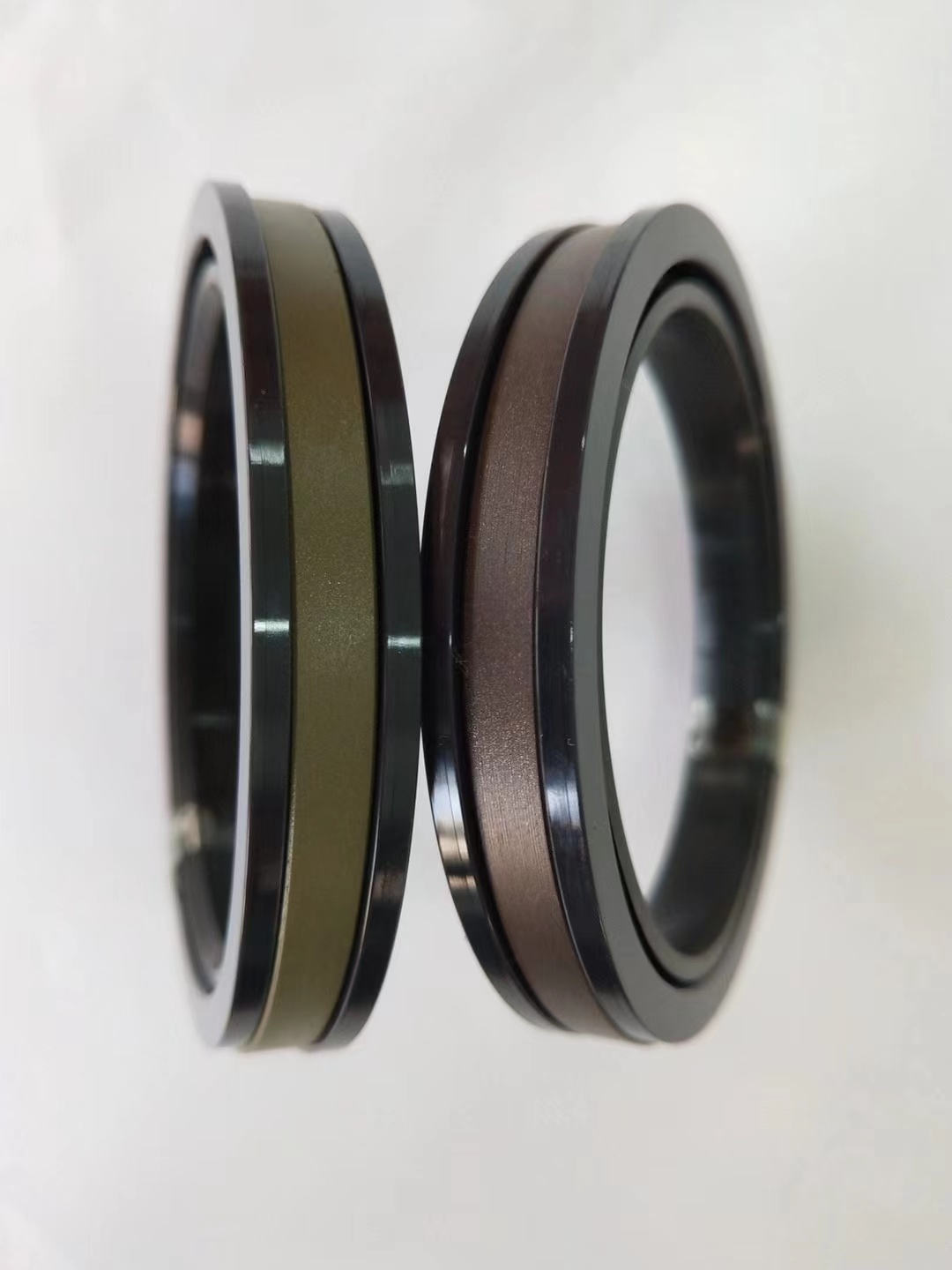
SPGW piston seal
Material:PTFE+rubber elastomer+reinforced modified nylon
Temperature:Nitrile rubber -40~100℃
Speed:=1.0m/s
Pressure:≤50mpa
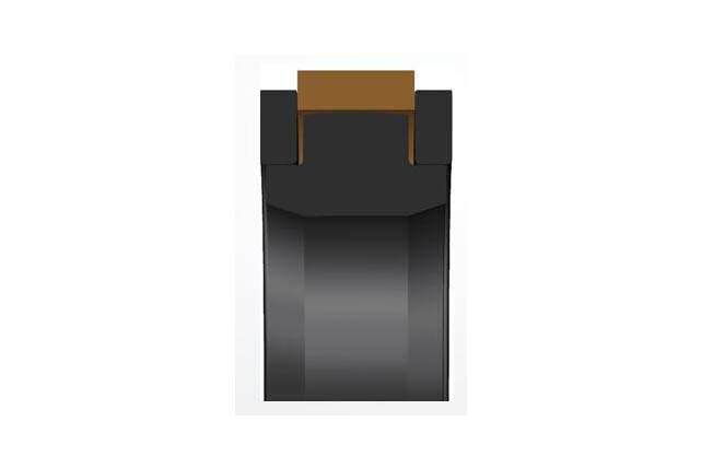
SPGO piston seal
Material:PTFE+rubber elastomer
Temperature:Nitrile rubber -40~110℃
Speed:=1.0m/s
Pressure:≤35mpa
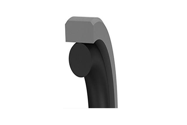
SRUV piston rod seal
Material:NBR+thermoplastic polyurethane
Temperature: -35`90℃
Speed:=0.5m/s
Pressure:≤40mpa
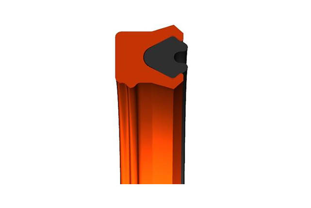
SRS piston rod seal
Material:PTFE+NBR
Temperature:-40~110℃
Speed:=1.0m/s
Pressure:≤40mpa
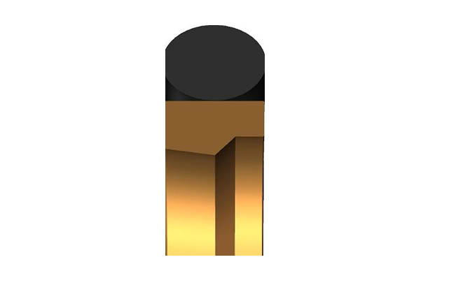
SRCB piston rod buffer seal
Material:Polyurethane+modified polyoxymethylene
Temperature: -35~110℃
Speed:=1.0m/s
Pressure:≤50mpa

SRU piston rod seal
Material:Polyurethane
Temperature:-35~100℃
Speed:=1.0m/s
Pressure:≤40mpa
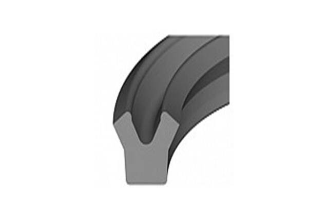
SRD iron case dust prevention
Material:Polyurethane+metal skeleton material
Temperature:-40~110℃
Speed:=1.0m/s
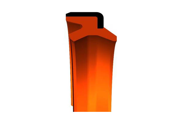
SRDI soft dustproof
Material:polyurethane
Temperature:-40~110℃
Speed:=1.0m/
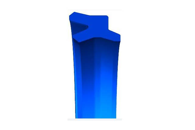
SDS Dumbbell Seal
Material:polyurethane
Temperature: -35~110℃
Speed:=0.5m/s
Pressure:≤50mpa

SPG piston combination seal
Temperature:
NBR+Polyurethane + Modified Polyoxymethylene
Temperature:-35`110℃
Speed:=0.3m/s
Pressure:≤70mpa
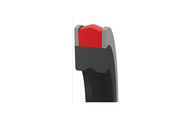
SRNL piston rod seal
Material
NBR+Polyurethane + Modified Polyoxymethylene
Temperature:-35`110℃
Speed:=0.3m/s
Pressure:≤70mpa
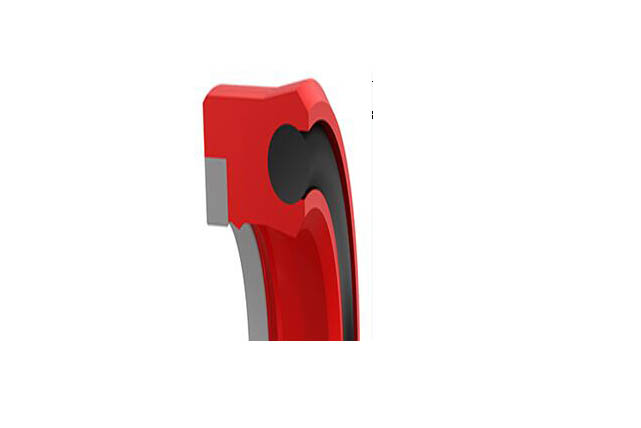
SRDF Piston Rod Seal
Material
Polyester rubber
Temperature:-40`100℃
Speed:=1.0m/s
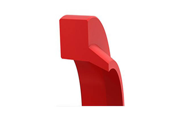
SDY Y-seal
Material:Polyurethane
Temperature:-35~110℃
Speed:=0.5m/s
Pressure:≤70mpa
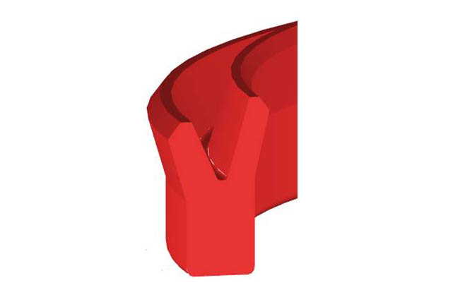
KZT anti fouling ring
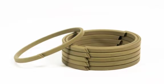
SDS Steffel
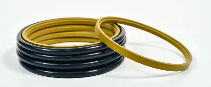
Piston main oil seal
