1. Product name: Epoxy Sticker,Epoxy Dome Stickers,Epoxy Resin Stickers,Epoxy Over Stickers Canton King Way Industrial Co., Limited , https://www.cantonkingway.com
Keywords: wire sawing machine; V360; frequency converter;
Introduction The electrical configuration of traditional diamond wire saws is generally through the PLC acquisition of current transformer analog signal to control the load of the main motor and the speed of the moving motor. The configuration of this method is more cumbersome, requires the participation of professional PLC programmers, resulting in a higher cost of the whole machine; and current transformers and analog input and output modules are easily damaged in the harsh environments such as mine water and dust. This article describes a kind of electric wire rope saw electric control system based on Quartet V360 frequency converter. The system omits the PLC and the current transformer. It also meets the technical requirements of the wire saw and reduces the cost.
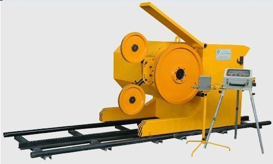
The composition and use of the wire sawing machine The diamond wire sawing machine (Fig. 1) is a kind of stone mining machine for mining quarries such as granite and marble. Diamond wire saws mainly include main motors, mobile motors, flywheels, guide wheels, chainsaw chains (made of diamond materials), mobile platforms, and operating platforms. Diamond wire saws are generally divided into four series: concrete, marble, granite, and heterosexual. 
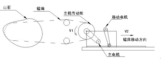
The diamond wire sawing machine uses the main motor to drive the sawing rope to run along an approximate track-type track. The sawing rope is put on the stone mountain that has been cut open, and the moving motor drives the whole sawing machine along the stone to be sawed at a certain speed through the speed reducer. Move backwards. The speed of movement must be adjusted in time according to the load condition of the main motor and the tension required by the sawing rope. If the moving speed is too fast, the load of the main motor increases or even overloads, the tension of the sawing rope will increase, if not. Adjusting the speed will break the saw rope. Conversely, if the moving speed is too slow, the tension of the sawing rope is too small, the sawing rope will slip on the stone, the cutting efficiency will be reduced, and the loose sawing rope will also be twisted to strand the sawing rope. Therefore, to ensure that the main motor load is basically uniform and the sawing rope is under proper tension, improving the cutting efficiency of the saw is the key to control. Due to the irregular shape of the mine, the cross-section is naturally large and small, and the sawing speed must be adjusted accordingly. The entire process is shown in Figure 2. 
Main motor power: 45KW, 380V, 8 poles, rated speed: 740 rpm, rated current 96A
Mobile motor power: 0.75KW, 380V, 4 pole, rated current 2.3A, frequency conversion motor main frequency conversion: V360-4T0550
Motor frequency conversion: E380-4T0015 
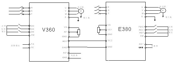
Electrical wiring diagram: 
Main motor frequency converter:
F0.2.25=9 External potentiometer setting frequency F0.3.33=1 External terminal start/stop F1.0.03=15 Acceleration time 15 seconds F1.0.04=15 Deceleration time 15 seconds F2.0.00=45 Motor rated power F2.0.01= 380 Rated motor voltage F2.0.02=96 Rated motor current F2.0.03=50 Rated motor frequency F2.0.04=740 Rated motor speed F4.2.22=2 ​​Analog output AO1 Select output Converter current F4.2.23=2 Analog output AO2 selection Output inverter current F4.2.24=0 Analog output AO1 minimum value is 0V
F4.2.25=10 The maximum value of analog output AO1 is 10V
F4.2.27=80% Analog output AO1 The upper limit of the assignment is 80% or 2 times the rated current F4.2.30=0 The minimum value of the analog output AO2 is 0V
F4.2.31=10 The maximum value of analog output AO2 is 10V
F4.2.32 = 33% The lower limit of the analog output AO2 is 96A (adjusted).
F4.2.33=100% Analog Output AO2 Inverter rated current 2.5 times F4.2.34=1 Analog output AO2 Filter time constant 1 second F8.1.21=0.8 Speed ​​closed loop gain F8.1.22=2.5 Speed ​​closed loop integral time FF .2.35=340 Undervoltage Action Level FF.3.38=2.00 Current Closed Loop Gain Movement Motor:
F0.1=8 frequency input channel combination setting F0.4=0001 external terminal start and stop F0.8=120 upper limit frequency 120HZ
F0.10=2 Acceleration time 2 seconds F0.11=2 Deceleration time 2 seconds F0.16=4 Carrier frequency 4K
F1.1=6 torque increase 6%
F2.12 = 5 external voltage VC1-VC2
V. Summary This article introduced a wire saw drive scheme based on the Quartet V360 frequency converter. This solution has the advantages of simple installation and debugging, while reducing the input of customer's electrical components. It has been successfully applied on diamond rope sawing machines of customers in Fujian Quanzhou and Laizhou Shandong. Can fully meet the requirements of working conditions, has been successfully applied to dozens of sets of wire saw machine terminal application site.
New Products Custom Waterproof 3D self adhesive Epoxy Resin Dome Label Sticker
2. Logo
Customized Logo
3. Material
Paper,PVC, PU,PP,PC,PET, Metal,etc
4. Size
Customeized Size
5. Thickness
0.2mm-2mm
6. Crafts
CMYK Printing, Epoxy
7. Grade
Echo friendly material+ High end quality
8. MOQ
500 pcs
9. Color
Pantone or customized
10. Characters
High quality, factory direct favourable price
Epoxy sticker are extremely durable, the colour can be 8-10 years outside with no colour fade, cost-effective and attractive labelling solutions. An extensive range of materials, finishes and production processes means they offer a versatile product that will clearly reflect the quality and style of your brand.
It with stronger 3M self adhesive, also colourful printing will make your brand logo be more interested in your market. Withstands even the most adverse environments. Chemical and scuff resistant.
Application of V360 Frequency Converter on Diamond Wire Sawing Machine
Abstract: This article describes the successful application of the Quartet V360 series frequency converter on a diamond wire saw.
Figure 1 Diamond Wire Saw
Process requirements: Figure 2 processing process
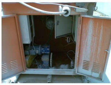
Third, V360 application program electrical configuration: Figure 3 application site map
IV. Commissioning scheme The actual operating current of the main motor is given to the mobile inverter VC2 as the dedicated PID feedback value via the analog AO2 output port, PID is used as the auxiliary frequency source, and the potentiometer is manually adjusted via the analog VC1 port to the mobile inverter as the main frequency source. The two frequency sources are superimposed as the output frequency of the moving motor, ie, the main frequency source plus the auxiliary frequency source. The moving speed of the moving motor is adjusted according to the feedback value of the host PID at any time to ensure that the current of the host is constant, and the speed of the host can be additionally given by a potentiometer. Advantages of the solution: The load control is stable and accurate, and the movement speed can be adjusted in time according to the change of the cutting surface, and the system fluctuation is small. Figure 4 Electrical wiring diagram
Debugging parameters: